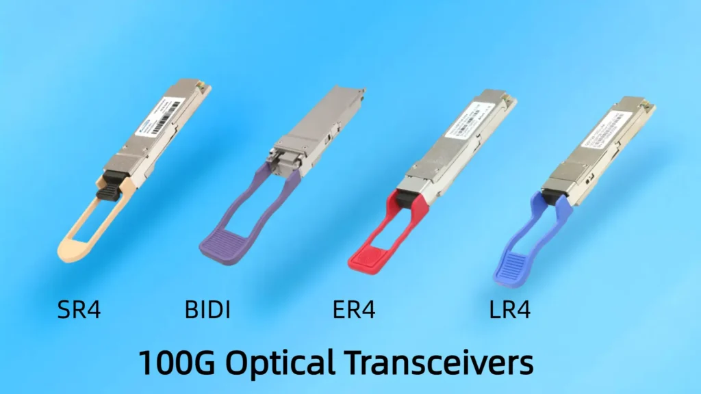
In today’s data‑driven world, network operators and enterprises demand ever‑higher bandwidth, lower latency, and greater link density. The 100G Optical Transceiver family has become the backbone of modern data centers, metro networks, and carrier infrastructures. Among these, the 100G QSFP28 Optical Transceiver variants stand out for their balance of performance, power efficiency, and form‑factor density. This guide covers four of the most common 100G QSFP28 transceiver types on the market:
100G QSFP28 BIDI Optical Transceiver
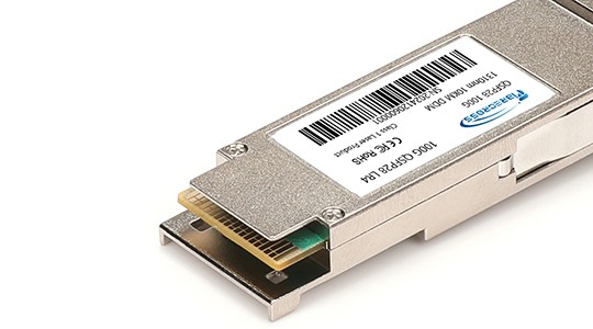
100G QSFP28 ER4 Optical Transceiver
100G QSFP28 LR4 Optical Transceiver
100G QSFP28 SR4 Optical Transceiver
We’ll explore each 100G Optical Transceiver Module, compare their features, and offer best‑practice recommendations to help you select the ideal solution for your network.
What Is a 100G Optical Transceiver Module?
A 100G Optical Transceiver Module is a hot‑pluggable device that converts electrical signals into optical signals—and vice versa—over fiber. In QSFP28 form factor, each lane operates at 25 Gbps, combining four parallel channels to achieve 100 Gbps aggregate throughput. These modules typically support Digital Diagnostic Monitoring (DDM) for real‑time insights into temperature, voltage, and optical power.
Key benefits of 100G optical transceivers include:
High Port Density: Four times the bandwidth of SFP28 in the same footprint.
Power Efficiency: Typically 3–5 W per port, helping minimize data‑center power and cooling costs.
Flexibility: Multiple variants support distances from 100 m to 40 km over multimode or single‑mode fiber.
100G QSFP28 BIDI Optical Transceiver
Overview
The 100G QSFP28 BIDI Optical Transceiver leverages bidirectional WDM on a single strand of single‑mode fiber. Two wavelengths (e.g., 1270 nm/1330 nm) carry transmit and receive channels, cutting fiber count in half compared to duplex solutions.
Key Features
Single‑Fiber, Duplex Operation: Simplifies cabling in fiber‑constrained environments.
Reach up to 10 km over G.652 SMF.
Power Consumption: ~4 W per 100G Optical Transceiver Module.
WDM Integration: Eliminates the need for separate Tx/Rx fibers.
Use Cases
Metro or campus links where fiber ducts are limited.
Data center interconnect (DCI) up to 10 km.
Retrofits of existing single‑strand fiber deployments.
Selection Tips
Verify fiber plant compatibility with WDM splitters.
Ensure link budget accounts for WDM insertion loss (~1 dB).
Match vendor‑specified wavelengths to avoid interoperability issues.
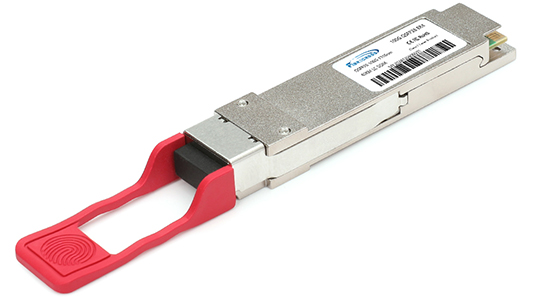
100G QSFP28 ER4 Optical Transceiver
Overview
For long‑haul applications, the 100G QSFP28 ER4 Optical Transceiver is engineered to span distances up to 40 km over standard G.652 single‑mode fiber. It employs four CWDM channels (1296.6 nm, 1300.5 nm, 1304.5 nm, 1308.5 nm), each transmitting 25 Gbps.
Key Features
Extended Reach: Supports up to 40 km without in‑line amplification.
Robust DDM: Monitors optical power, temperature, and voltage.
Low Dispersion Penalty: Optimized lasers minimize chromatic dispersion over long runs.
Power Draw: ~5 W per module.
Use Cases
Inter‑city fiber links in metro‑area networks (MAN).
Carrier and service‑provider backbone routes.
Campus backbone connections.
Selection Tips
For links >30 km, consider dispersion compensation modules.
Calculate total optical budget: fiber attenuation (~0.4 dB/km) + connector/splice losses (0.5 dB each).
Budget for slightly higher part cost due to advanced DSP and laser requirements.
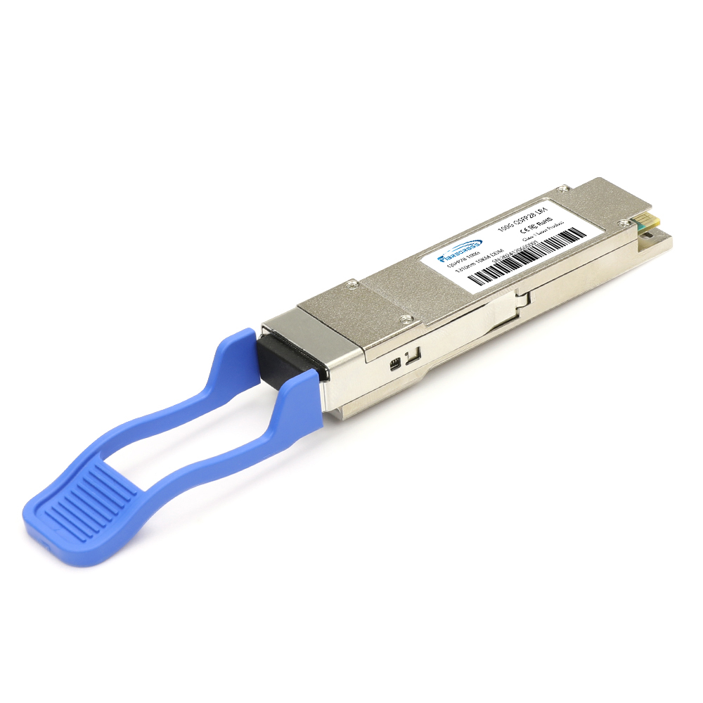
100G QSFP28 LR4 Optical Transceiver
Overview
The 100G QSFP28 LR4 Optical Transceiver is the workhorse for single‑mode links up to 10 km. Like ER4, it uses four CWDM wavelengths (1271 nm, 1291 nm, 1311 nm, 1331 nm), but with optimized optics for metro‑scale reach.
Key Features
10 km Reach: Ideal for intra‑ and inter‑data center links within the same metro area.
4 × 25 Gbps Channels: Aggregated into a single QSFP28 port.
Compact Power Budget: ~3.5–4.5 W per 100G Optical Transceiver.
Hot‑Swappable: No need to power down equipment during installation.
Use Cases
Spine‑leaf and core‑edge connections in data centers.
Building‑to‑building links on enterprise campuses.
Router‑to‑router metro core connections.
Selection Tips
Confirm switch firmware compatibility with third‑party modules.
Use industrial‑grade versions for uncontrolled environments.
Test existing fiber for return‑loss compliance (<–14 dB) to avoid link failures.
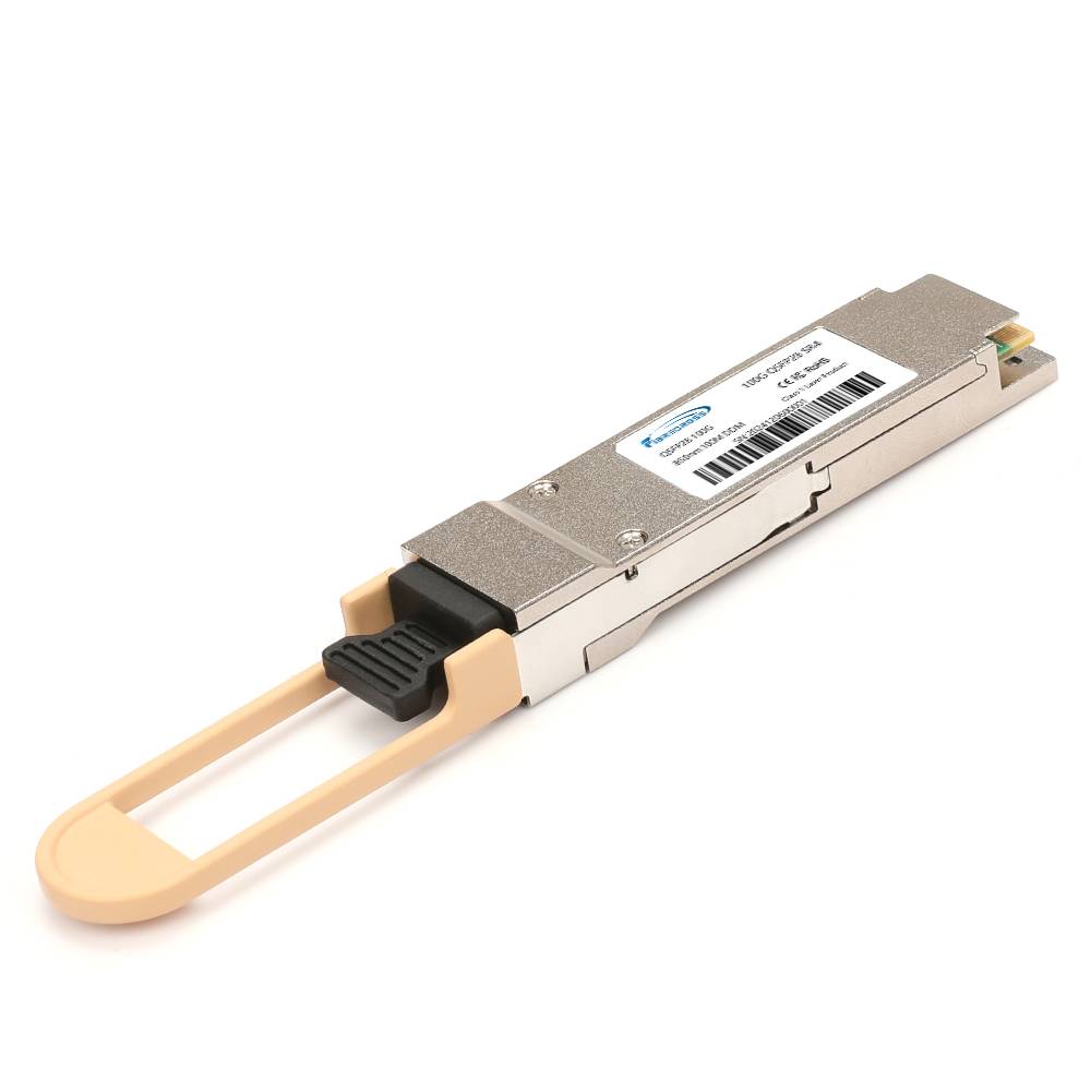
100G QSFP28 SR4 Optical Transceiver
Overview
Within rack and adjacent‑rack connections, the 100G QSFP28 SR4 Optical Transceiver reigns supreme. It delivers up to 100 m over multimode fiber (MMF) using an 8‑fiber parallel design (4 Tx, 4 Rx) in an MPO/MTP interface.
Key Features
Short‑Reach Focus: Perfect for top‑of‑rack (ToR) to leaf‑switch links.
Low Latency: Direct optical path minimizes delay.
Cost‑Effective: Lower module cost and fiber‐plant expense.
Power Efficiency: <3.5 W per 100G Optical Transceiver Module.
Use Cases
Intra‑rack and neighboring‑rack connections in data centers.
Fibre Channel over Ethernet (FCoE) for storage networks.
High‑performance computing (HPC) clusters requiring minimal latency.
Selection Tips
Prefer OM4 (100 m) over OM3 (70 m) for guaranteed reach.
Maintain MPO/MTP polarity to avoid Tx/Rx mismatches.
Clean fiber end faces meticulously to prevent power penalties.
Comparative Table
| Specification | BIDI | ER4 | LR4 | SR4 |
|---|---|---|---|---|
| Form Factor | QSFP28 | QSFP28 | QSFP28 | QSFP28 |
| Medium | SMF (single‑strand) | SMF (duplex, 4 strands) | SMF (duplex, 4 strands) | MMF (MPO/MTP) |
| Reach | ≤ 10 km | ≤ 40 km | ≤ 10 km | ≤ 100 m |
| Wavelengths | 2 WDM channels | 4 CWDM channels | 4 CWDM channels | 4 Parallel MMF lanes |
| Connector | LC Duplex | LC Duplex | LC Duplex | MPO/MTP |
| Typical Power | ~4 W | ~5 W | ~4 W | ~3.5 W |
| Use Case | Fiber‑constrained runs | Long‑haul metro/backbone | Metro/data‑center links | Intra‑data‑center links |
| Keyword Example | “100G Optical Transceiver” | “100G QSFP28 Optical Transceiver ER4” | “100G Optical Transceiver Module LR4” | “100G QSFP28 SR4 Transceiver” |
How to Choose the Right 100G Optical Transceiver
When evaluating which 100G Optical Transceiver Module to deploy, weigh these factors:
Link Distance
≤ 100 m over MMF → SR4
≤ 10 km over SMF → LR4 or BIDI
10–40 km over SMF → ER4
Fiber Infrastructure
Single‑ versus duplex‑strand fiber
Availability of MPO/MTP trunks or LC duplex patch panels
Total Cost of Ownership
Module price vs. additional fiber or splitters
Power consumption (impacts cooling budget)
Long‑term scalability to 400G/800G form factors
Vendor Ecosystem
Interoperability and warranty
Firmware support and compatibility lists
Availability of third‑party vs. OEM modules
Future Growth
Ability to reuse existing fiber for higher speeds
Support for DWDM channels or PAM4 modulation in next‑gen modules
Implementation Best Practices
Pre‑Deployment Testing: Perform optical time‑domain reflectometer (OTDR) and insertion‑loss measurements.
Cable Management: Label every fiber and secure patch cords to prevent accidental unplugging.
Environmental Controls: Monitor ambient temperature and humidity in equipment rooms.
Monitoring and Alerts: Utilize DDM alarms for optical power thresholds and temperature excursions.
Firmware Updates: Keep switch and host‑board firmware updated for maximum transceiver compatibility.
Frequently Asked Questions
Q1: Can I use 100GBASE‑SR4 and 100GBASE‑LR4 modules on the same switch?
Yes—most modern switches accept mixed QSFP28 types on different ports, as long as each port’s optics are supported by the host’s compatibility matrix.
Q2: What are common DDM parameters for a 100G QSFP28 Optical Transceiver?
Typical DDM data include Tx/Rx optical power, bias current, temperature, supply voltage, and laser lane health.
Q3: Is there a 100G optical transceiver module for distances between 100 m and 10 km on MMF?
Variants like 100GBASE‑PSM4 and CWDM4‑MM extend multimode reach to 500 m or beyond but use specialized MPO cabling and may require additional MUX/DEMUX gear.
Conclusion
The versatility of the 100G Optical Transceiver family—spanning SR4 for ultra‑short reach, LR4/BIDI for metro 10 km links, and ER4 for up to 40 km—ensures there’s a QSFP28 solution for every use case. By aligning your fiber‑plant characteristics, distance requirements, and budget considerations, you can select the optimal 100G QSFP28 Optical Transceiver or 100G Optical Transceiver Module to future‑proof your network.
Ready to upgrade your bandwidth? Contact our network experts at fibercross to explore the full lineup of 100G QSFP28 transceivers and architect a robust, scalable 100 Gbps infrastructure.