Introduction to 400GBASE-DR4
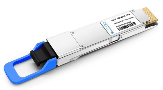
In the era of ever‑increasing data demands, the 400GBASE-DR4 transceiver has emerged as a cornerstone technology for modern data centers. A 400G DR4 Optical Transceivers module aggregates four independent 100 Gbps lanes—each modulated with PAM4 (4‑level Pulse Amplitude Modulation) on a 1310 nm wavelength—and transmits them in parallel over standard single‑mode fiber (SMF) up to 500 m. Housed in a compact QSFP‑DD (Quad Small Form‑factor Pluggable Double‑Density) package, these Optical Transceivers deliver hot‑pluggable, scalable 400 GbE connectivity, meeting the bandwidth needs of hyperscale cloud, AI clusters, and spine‑leaf architectures.
Key Technical Features of 400G DR4 Optical Transceivers
| Feature | Detail |
|---|---|
| Data Rate | 400 Gbps aggregate via four 100 Gbps lanes (PAM4) |
| Modulation | PAM4 doubles bits per symbol, enabling higher spectral efficiency without raising symbol rates |
| Wavelength | 1310 nm for low chromatic dispersion and ~0.35 dB/km attenuation |
| Reach | Up to 500 m on G.652‑compliant SMF |
| Connector | MPO‑12 for eight active fibers (4 TX, 4 RX) in a single plug |
| Form Factor | QSFP‑DD: double‑density QSFP; backward‑compatible with QSFP28/56 |
| Power Consumption | Typically ≤ 12 W per module |
| Diagnostics | Digital Diagnostic Monitoring (DDM) for optical power, temperature, voltage, and bit‑error monitoring |
| Standards Compliance | IEEE 802.3bs/802.3cd for 400 GbE; SFF‑8636 (CMIS) for manageability and interoperability |
Why These Features Matter for Engineers
High Density: QSFP‑DD’s double‑row contacts allow up to 36 ports per 1 RU switch, maximizing rack‑unit efficiency.
Energy Efficiency: PAM4’s spectral efficiency keeps power consumption under 12 W, reducing cooling requirements.
Modular Scalability: Hot‑pluggability lets network teams upgrade link speeds without replacing entire line cards.
Maximizing Reach and Performance with Optical Transceivers
PAM4 Encoding and 1310 nm Advantages
The heart of every 400GBASE-DR4 transceiver lies in its PAM4 DSP engine, which maps 2 bits per symbol. This enables 100 Gbps lanes without a proportional increase in electrical bandwidth—critical for controlling power and thermal budgets. Operating at 1310 nm leverages the low‑dispersion window of SMF, where chromatic dispersion is minimal, and attenuation is modest at ~0.35 dB/km. Together, these factors ensure stable, high‑integrity 400 Gbps links across the data‑center fabric.
Best Practices for MPO‑12 Cabling
Fiber Type: Use OS2, ITU‑G.652.D single‑mode fiber rated for low loss.
Connector Hygiene: Regularly clean MPO‑12 ferrules to prevent insertion‑loss spikes.
Polarity Management: Employ Type A polarity trunks and compatible MPO‑LC breakout cables to correctly map TX/RX lanes.
Loss Budget: Aim for <1 dB end‑to‑end loss; account for connector/mating and splice losses.
Form Factors and Compatibility: QSFP‑DD vs OSFP
| Characteristic | QSFP‑DD DR4 Transceivers | OSFP DR4 Transceivers |
|---|---|---|
| Module Size | Compact, QSFP‑compatible cage | Larger, integrated heatsink design |
| Power Envelope | ≤ 12 W | Up to ~15 W or higher |
| Port Density | Very high (more per RU) | Moderate (due to larger module footprint) |
| Cooling Profile | Standard switch airflow | Enhanced heat dissipation via heatsink |
| Future‑proofing | 400 GbE only | Can accommodate upcoming 800 GbE optics |
Integration Tips for Multi‑Vendor Environments
Standards Compliance: Only deploy modules certified to IEEE 802.3bs/802.3cd and CMIS.
Switch Firmware: Ensure firmware supports QSFP‑DD CMIS register sets and 400 GBASE‑DR4 lane mapping.
“Generic‑Compatible” Options: Reputable third‑party optics can emulate OEM vendor codes, offering cost savings without sacrificing interoperability.
Alternative 400G Standards
| Standard | Fiber Type | Max Reach | Modulation | Connector |
|---|---|---|---|---|
| 400GBASE-DR4 | SMF (G.652) | 500 m | PAM4 × 4 lanes | MPO‑12 |
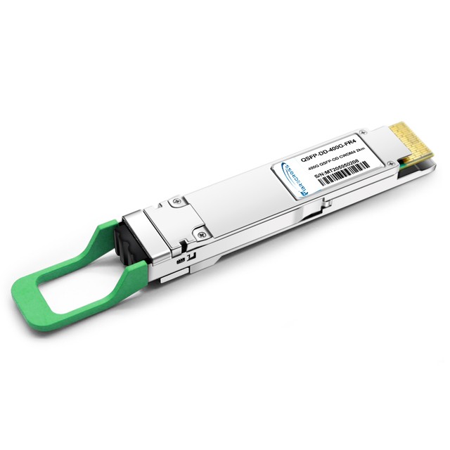
| 400GBASE-FR4 | SMF (G.652) | 2 km | PAM4 + CWDM × 4 | LC duplex |
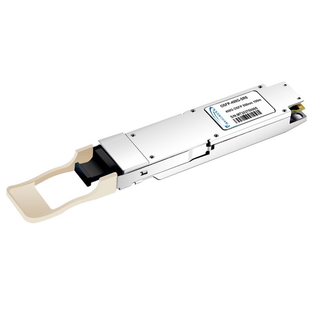
| 400GBASE-SR4 | MMF (OM4/OM5) | 70–100 m | NRZ × 4 lanes | MPO‑12 |
DR4: Optimal for medium‑reach, high‑density leaf‑spine links using 400G DR4 Optical Transceivers.
FR4: Extends reach to ~2 km via coarse WDM, suited for multi‑building or campus links.
SR4: Targets short MMF runs in top‑of‑rack and server‑to‑TOR connections.
Deployment Considerations and Best Practices
Port Density vs. Reach:
Choose 400GBASE-DR4 transceiver for dense, ≤500 m links.
Opt for FR4 or LR4 optics if distances exceed 500 m.
Cabling Infrastructure:
Standardize on MPO‑12 trunks.
Plan breakout harnesses that split into four duplex LC pairs for seamless field upgrades.
Thermal Management:
Verify switch airflow meets QSFP‑DD power profiles.
Consider OSFP DR4 heatsink modules in high‑density, high‑power racks.
Interoperability:
Audit switch compatibility lists for Optical Transceivers.
Test third‑party optics in lab before production deployment.
Monitoring and Maintenance:
Leverage DDM to track optical power, temperature, and voltage trends.
Schedule periodic fiber inspections and cleaning to maintain loss budgets.
Future Trends in High‑Speed Optical Transceivers
The data‑center industry is rapidly evolving toward 800G and 1.6T Ethernet. IEEE 802.3df is defining new PHYs—such as 800G‑DR4 (8×100 Gbps lanes over 500 m) and 800G‑FR4 (2 km)—that build upon DR4 principles but double the lane count. To support these speeds, the community is developing new pluggable form factors:
QSFP‑DD800: An extension of QSFP‑DD for eight‑lane optics.
OSFP800: Larger “800G‑ready” cages with robust thermal headroom.
Despite next‑gen speeds, parallel optical designs (MPO‑based) will continue to dominate intra‑data‑center links, thanks to proven reliability and density. Meanwhile, single‑lambda coherent modules may handle metro and long‑haul segments. As you plan your network evolution, factor in fiber‑plant readiness: deploying duplex SMF today paves the way for both parallel and coherent upgrades tomorrow.
Conclusion
Embedding 400GBASE-DR4 transceiver, 400G DR4 Optical Transceivers, and general Optical Transceivers terminology throughout this article highlights their pivotal role in high‑speed data‑center networks. By understanding the technology’s core—PAM4 modulation, 1310 nm wavelength, MPO‑12 cabling, and QSFP‑DD/OSFP form factors—engineers can confidently design, deploy, and scale 400 GbE infrastructures today, and seamlessly transition to 800 GbE and beyond.