400G Direct Attach Cables: Performance & Deployment Tips

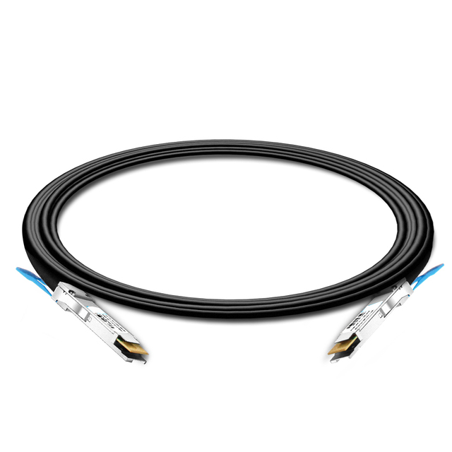
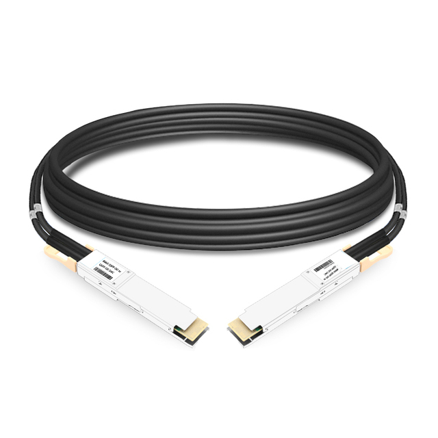
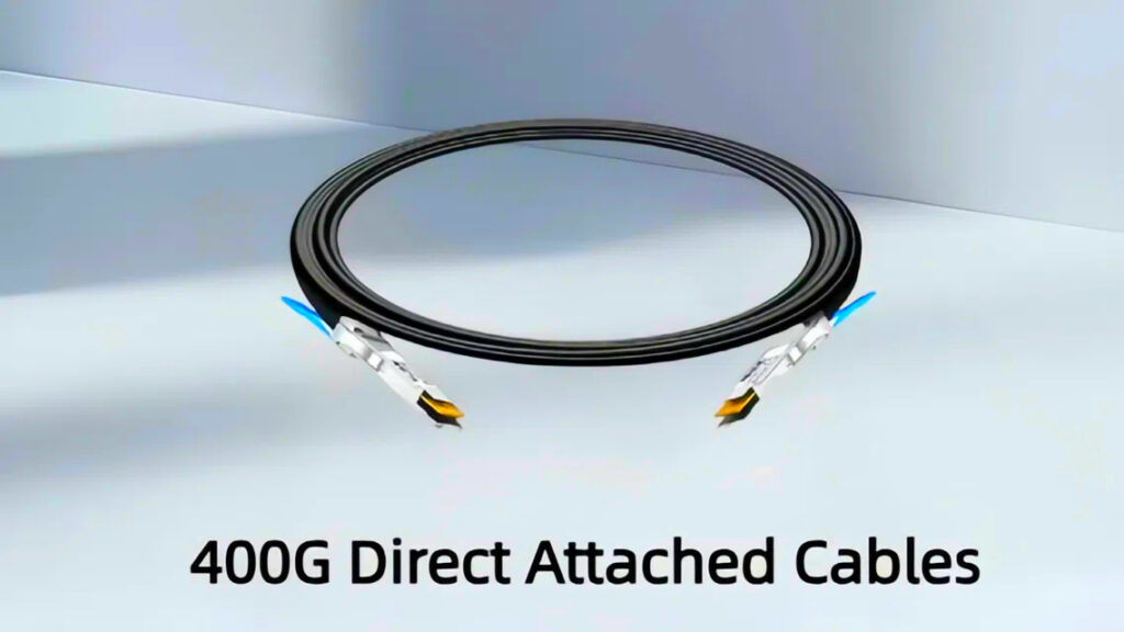
As data centers and high-performance networks demand ever-increasing bandwidth and lower latency, 400G interconnect solutions have become mainstream. For short-reach scenarios, 400G Direct Attach Copper (DAC) cables offer ultra-low latency, low power consumption, and cost advantages. They are widely used for connections within a rack or between adjacent racks, linking switches, servers, and storage devices. This article addresses network engineers, providing an in-depth look at 400G Direct Attach Cables: definition and types, structure and operation principles, key performance characteristics, comparison with 400G AOC, deployment scenarios, and best practices for design and selection.


400G Direct Attached Cable


1. Definition and Types

 What Is a 400G DAC Cables?

  • Definition
    A 400G direct attached cables is a twinax copper cable assembly with integrated 400G-capable interfaces (such as QSFP-DD or OSFP) at both ends. Each connector plugs directly into a 400GbE-capable port on a switch, NIC, or other network device. There is no separate optical transceiver module involved.

  • Typical Scenarios
    Suited for short-distance high-bandwidth, low-latency links (usually within a few meters), such as uplinks or aggregation links in leaf-spine architectures, HPC cluster interconnects, and financial trading environments.


Main Variants

  1. By Signal Handling: Passive vs. Active DAC

    • Passive DAC Cable: The cable consists solely of copper conductors and shielding, without onboard signal-conditioning electronics. Advantages: very low cost, negligible power draw. Limitation: reach is constrained to a few meters.

    • Active DAC Cable: Embeds signal-conditioning circuitry (equalization, pre-emphasis, retiming) or even electro-optical conversion at one or both ends, enabling longer reach (around 5–10 meters) at higher cost and power consumption.

  2. By Interface Form Factor: QSFP-DD, OSFP, etc.

    • QSFP-DD DAC Cable: Common for devices supporting QSFP-DD ports; carries eight differential channels, each at 50 Gb/s (PAM4), totaling 400 Gb/s.

    • OSFP DAC : Another 400G form factor; the mechanical dimensions differ but the principle is analogous. Compatibility depends on the device’s supported module type.

  3. By Function: Direct Attach vs. Breakout

    • Direct Attach: Both ends have 400G connectors, linking two 400G ports directly.

    • Breakout DAC: One end is a 400G connector; the other end fans out to multiple lower-rate ports (e.g., 2×200G, 4×100G, or 8×50G). This allows a single 400G port to interconnect with multiple legacy or lower-speed ports, useful for upgrades or heterogeneous equipment integration.


Structure and Operation Principles

Physical Construction

  • Shielded Twinax Pairs
    Each differential pair consists of two tightly twisted copper conductors wrapped in shielding (braid or foil) to minimize crosstalk and electromagnetic interference. A QSFP-DD DAC typically contains eight such differential pairs for data lanes.

  • Connector Assemblies
    The housing resembles that of optical transceiver modules, but internally connects directly to copper pairs. In active DACs, small circuits within the connector handle signal equalization or conversion; passive DAC connectors simply make direct electrical contact to the copper.

Signal Transmission

  • PAM4 Modulation
    To achieve 50 Gb/s per lane over copper, PAM4 (4-level pulse-amplitude modulation) is employed. Compared to NRZ, PAM4 doubles bit density per symbol but demands higher signal integrity and SNR.

  • Impedance and Loss Control
    Design ensures consistent 100 Ω differential impedance throughout the path to reduce reflections. High-purity copper, precise twisting, and thorough shielding help limit insertion loss and crosstalk. Passive DAC attenuation restricts reach (typically up to ~3 m); active DAC modules incorporate equalization and/or retiming to support several more meters while maintaining acceptable bit-error rates.

  • Power and Thermal Considerations

    • Passive DAC: Virtually zero onboard power draw; only the host PHY drives the signals.

    • Active DAC: Requires power for signal-conditioning electronics (and possibly optical components), typically a few watts. Compared to active optical cables or discrete optics, active DAC power is moderate but significantly higher than passive.

Interoperability and Standards

  • IEEE Compatibility
    Compliant with IEEE 802.3bs/802.3cd (400GbE) electrical specifications to ensure correct rate and signal characteristics.

  • Multi-Source Agreements (MSA)
    QSFP-DD/OSFP DACs follow MSA guidelines for dimensions, pin assignments, and electrical requirements, ensuring cross-vendor compatibility.

  • Testing and Certification
    Manufacturers test DACs for insertion loss, return loss, crosstalk, insertion/removal cycles, etc. Device vendors run compatibility tests (e.g., link-up, BER under load) to verify that specific DACs function correctly with their switches or NICs.

 400G QSFP-DD DAC copper cable for short-range server connectivity


Key Features and Performance

Bandwidth and Latency

  • 400 Gb/s Aggregate Throughput
    Achieved via eight parallel 50 Gb/s differential lanes, meeting the demands of modern east-west and north-south traffic in data centers and high-performance fabrics.

  • Ultra-Low Latency
    Passive copper links add only nanoseconds of propagation delay (approximately 4–5 ns per meter). This minimal latency is critical for latency-sensitive applications (e.g., high-frequency trading, real-time analytics).

Power Consumption and Cooling

  • Passive DAC
    Negligible power draw (typically under 0.2 W per end), imposing almost no additional cooling burden.

  • Active DAC
    Consumes several watts due to signal-conditioning or optical components. Though lower than many active optical cable solutions, planning power budget and rack cooling remains important.

Density and Manageability

  • Size and Weight
    Copper twinax is thicker and heavier than fiber, but connectors fit into the same ports as optical modules. When deploying many DACs, consider cable diameter, bend radius, and mechanical support. Proper cable routing and management structures help maintain order and airflow.

  • Durability and Reliability
    High-quality DACs are rated for many insertion/removal cycles. Copper cabling in short-reach environments is mechanically robust and less fragile than fiber, though care is still needed to avoid severe bending or damage to shielding.

Cost Efficiency

  • Lower Unit Cost
    Without optical transceivers or lasers, DACs have significantly lower BOM and manufacturing costs compared to active optical cables or discrete optics.

  • Reduced Operational Expense
    Low power consumption and minimal cooling needs lower operational costs. No fiber-endface cleaning is needed, simplifying maintenance.

Reach Limitations

  • Passive DAC: Typically guaranteed up to around 1–3 meters (some high-end cases may extend to 5–7 meters under ideal conditions, though sticking within standard range ensures reliability).

  • Active DAC: With onboard equalization or electro-optical conversion, can support longer distances (around 5–10 meters), but at higher cost and power.

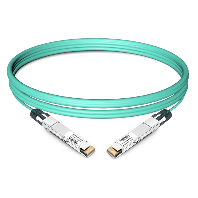
  • In Comparison to AOC or Discrete Optics: Optical solutions can span tens to hundreds of meters, but incur higher latency, power, and cost for short links.

Comparison with 400G AOC Cables

Aspect400G Direct Attached Cables (DAC)400G Active Optical Cables (AOC)
Transmission MediumPure copper twinax; passive variants have no optics; active variants include signal-conditioning electronics only.Fiber optic medium; both ends house lasers, photodetectors, and related electronics.
Reach– Passive DAC: typically up to ~1–3 m (sometimes extended to ~5–7 m under ideal conditions, but not generally recommended beyond ~3 m for reliability).- Active DAC: can reach ~5–10 m with onboard equalization or electro-optical conversion, at higher cost/power.– Multimode AOC: tens of meters (e.g., ~70–100 m on OM3/OM4).- For longer spans beyond AOC, discrete optical transceivers + separate fiber runs are used.
LatencyUltra-low: no optical conversion, only copper propagation delay (~4–5 ns per meter). Ideal for latency-sensitive applications.Higher: includes electrical–optical and optical–electrical conversion plus fiber propagation; adds several nanoseconds (or more depending on distance) compared to DAC.
Power Consumption– Passive DAC: negligible (virtually zero beyond host PHY drive).- Active DAC: a few watts for signal-conditioning; still lower than many optical solutions.Generally several watts per link due to lasers and optics; power > active DAC variants.
CostLower unit cost, especially passive variants. Lower total cost of ownership for short links.Higher cost due to optical components and assembly; TCO higher for short distances.
Cable Size & WeightThicker and heavier than fiber; connectors fit same ports as optical modules. Requires attention to bend radius and routing in dense cabling.Thinner and lighter fiber; smaller bend radius makes routing easier in dense environments. Fiber is more sensitive to bending damage and requires endface cleanliness.
EMI ImmunityShielded but copper can pick up EMI if not well managed; in short-reach with good shielding, performance is acceptable.Fiber is dielectric—intrinsically immune to EMI; preferred in high-EMI environments.
Mechanical RobustnessCopper twinax is mechanically robust, less fragile than fiber; but avoid severe bends or crushing.Fiber is more fragile—sensitive to tight bends, kinks, and requires endface cleaning/inspection.
Use Case SuitabilityVery short links within a rack or between adjacent racks where ultra-low latency, low power, and cost-efficiency are critical.Short-to-medium links (tens of meters) where lighter cabling, moderate latency, or EMI immunity are required, accepting higher power/cost.


400G QSFP-DD DAC cable compatible with NVIDIA QM9700 for data center interconnects


Deployment Scenarios and Selection Guidance

Typical Use Cases

  1. In-Rack Interconnect

    • Leaf-spine architectures: connecting top-of-rack (ToR) switches to aggregation or spine switches within the same rack.

    • High-bandwidth links between servers and storage nodes located in the same chassis or rack.

  2. Adjacent Rack Links

    • Direct connections between neighboring racks in a data center. If distance slightly exceeds passive DAC reach, consider active DAC or AOC.

  3. High-Performance Computing (HPC) Clusters

    • Links between compute nodes or between compute and I/O nodes, where low latency and high throughput are essential.

  4. Financial Trading Environments

    • Ultra-low-latency connections within the same rack or facility, leveraging passive DAC to minimize propagation delay.

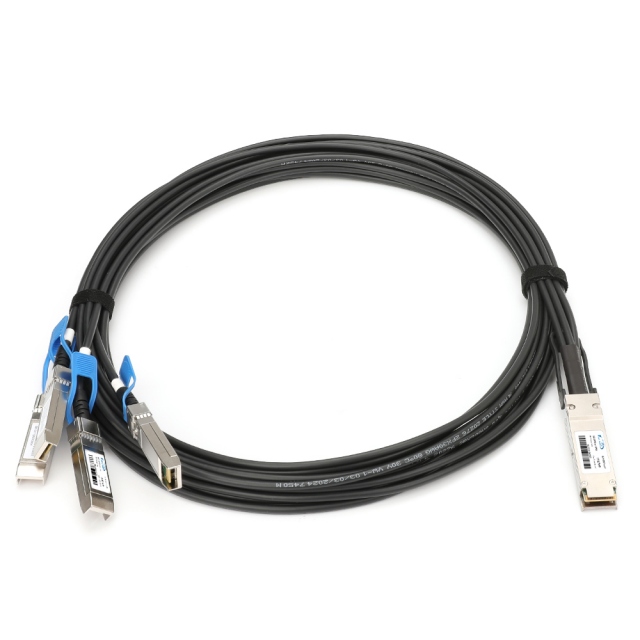
  5. Mixed-Rate Interconnect (Breakout)

    • During network upgrades, fan out a 400G port into multiple lower-speed links (e.g., 4×100G) to interface with existing equipment or distributed services.

  6. Edge or Small Data Center Deployments

    • Small footprint environments requiring high bandwidth over short distances; passive or active DAC reduces cost and simplifies maintenance compared to fiber.

Selection Considerations

  • Distance Assessment: Measure actual separation between devices. Prefer passive DAC when within its guaranteed reach. If slightly beyond (e.g., 5–7 m), evaluate active DAC with attention to power and cost. For longer spans, switch to AOC or discrete optics with fiber.

  • Compatibility Checks: Ensure the switch, NIC, or device supports the chosen interface type (QSFP-DD, OSFP, etc.) and that the DAC’s electrical characteristics match device requirements. Review vendor compatibility lists or run interoperability tests.

  • Cabling and Management: Plan cable pathways early. Observe minimum bend radius and avoid over-compression. For high-density DAC deployments, employ cable management trays or guides so that maintenance or scaling remains straightforward.

  • Power and Cooling: Passive DAC has negligible power impact. Active DAC or optical solutions require power budgeting and checking rack cooling capacity.

  • Reliability and Maintenance: Select cables from reputable vendors with quality assurance and lifetime guarantees. Although copper DAC requires less cleaning than fiber, avoid excessive bending or physical damage. Keep records of insertion/removal cycles and performance metrics.

  • Cost Analysis: At scale, passive DAC offers significant savings. Factor in device compatibility, power, cooling, and maintenance when evaluating total cost of ownership.

  • Testing and Validation: Before and after deployment, perform link tests: rate negotiation verification, BER measurement, eye-diagram or jitter analysis. For large deployments, consider automated test tools for batch validation.

6. Installation, Testing, and Operations

Installation Procedure

  1. Preparation: Ensure devices are either powered down or ports support hot-plug. Inspect cable and connectors for any physical damage.

  2. Insertion: Align the DAC connector with the port and insert until latch or guide engages. No tools are needed.

  3. Securing and Routing: Use cable management hardware or Velcro straps (not too tight) to route the cable within the rack, honoring bend-radius guidelines.

  4. Power On and Link Verification: Power up equipment. Check device interface status to confirm auto-negotiation to 400GbE and verify traffic flow.

Link Testing

  • Basic Connectivity: Use ping, iperf, or equivalent tools to validate throughput and latency.

  • Signal Integrity and BER: Employ dedicated test instruments or built-in diagnostics to measure bit-error rate, eye height, jitter, etc., ensuring compliance with specifications.

  • Interoperability Verification: In multi-vendor environments, test the DAC with various vendor equipment combinations under typical load and redundancy protocols (e.g., LACP, MLAG) to ensure stability.

Maintenance and Troubleshooting

  • Common Issues

    • Loose or corroded connector: inspect and reseat the cable.

    • Exceeding distance or mismatched electrical specs: if instability or high BER occurs, confirm distance within spec; consider higher-grade or active DAC/AOC.

    • Port configuration errors: verify switch/NIC settings (speed, forward-error-correction, link aggregation settings, etc.).

  • Troubleshooting Workflow

    1. Check port status indicators, device logs, or alarms.

    2. Physically inspect cable for bends, crushing, or shielding damage.

    3. Review switch or NIC error counters (packet drops, CRC errors).

    4. Test the same cable on a known-good port or device to isolate cable vs. port issue.

    5. If unresolved, use scope or signal analyzer to inspect eye diagrams and jitter.

    6. Replace cable or module to confirm whether the fault follows the cable.

  • Routine Maintenance

    • Passive DAC: mainly ensure proper insertion and avoid excessive bending; minimal ongoing upkeep.

    • Active DAC/AOC: monitor power consumption and temperature; apply firmware updates if supported by vendor; periodically review performance metrics to detect degradation.

    • Maintain records of link performance, test results, and any replacements to assist capacity planning and trend analysis.


7. Conclusion

400G direct attached cables offer unique advantages in short-reach, high-bandwidth scenarios: ultra-low latency, minimal power consumption, cost-efficiency, and straightforward deployment with high-density ports. Network engineers designing data center interconnects or high-performance fabrics should prioritize passive DAC when distances permit; if reach slightly exceeds passive limits, active DAC is an option; for longer spans or where lighter cabling or superior EMI immunity is required, optical solutions should be chosen.

Related Products